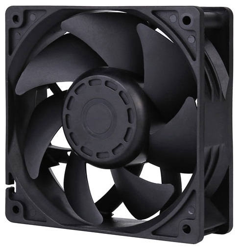
MFE12038
Product Specifications
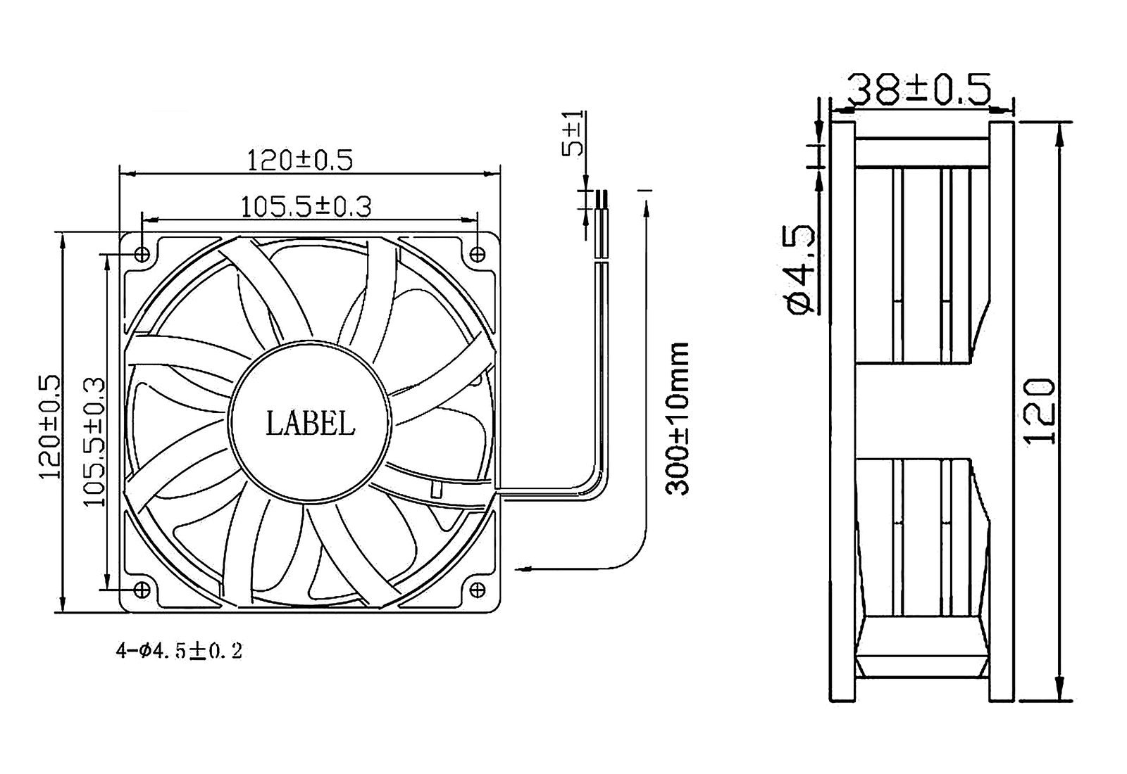
| Size | : 120x 120 x 38mm |
| Voltage | AC 100~277V |
| Motor | EC (Electronically Commutated) |
| Frame | plastic PBT UL94V-0 |
| Impeller | plastic PBT UL94V-0 |
| Bearing Type | Ball Bearing / Sleeve Bearing |
| Operating Temperature | Ball Bearing: -10 ~ 70°C / Sleeve Bearing: 0 ~ 60°C |
| Life Expectancy | Ball Bearing: 50,000 hours at 25°C / Sleeve Bearing: 30,000 hours at 25°C |
Part Number & Specifications
| Model | Rated Voltage (V) | Operating Voltage Range (V) | Input Power (W) | Speed (RPM) | Max. Airflow (CFM) | Max. Pressure (mmH₂O) | Noise (dB-A) |
|---|---|---|---|---|---|---|---|
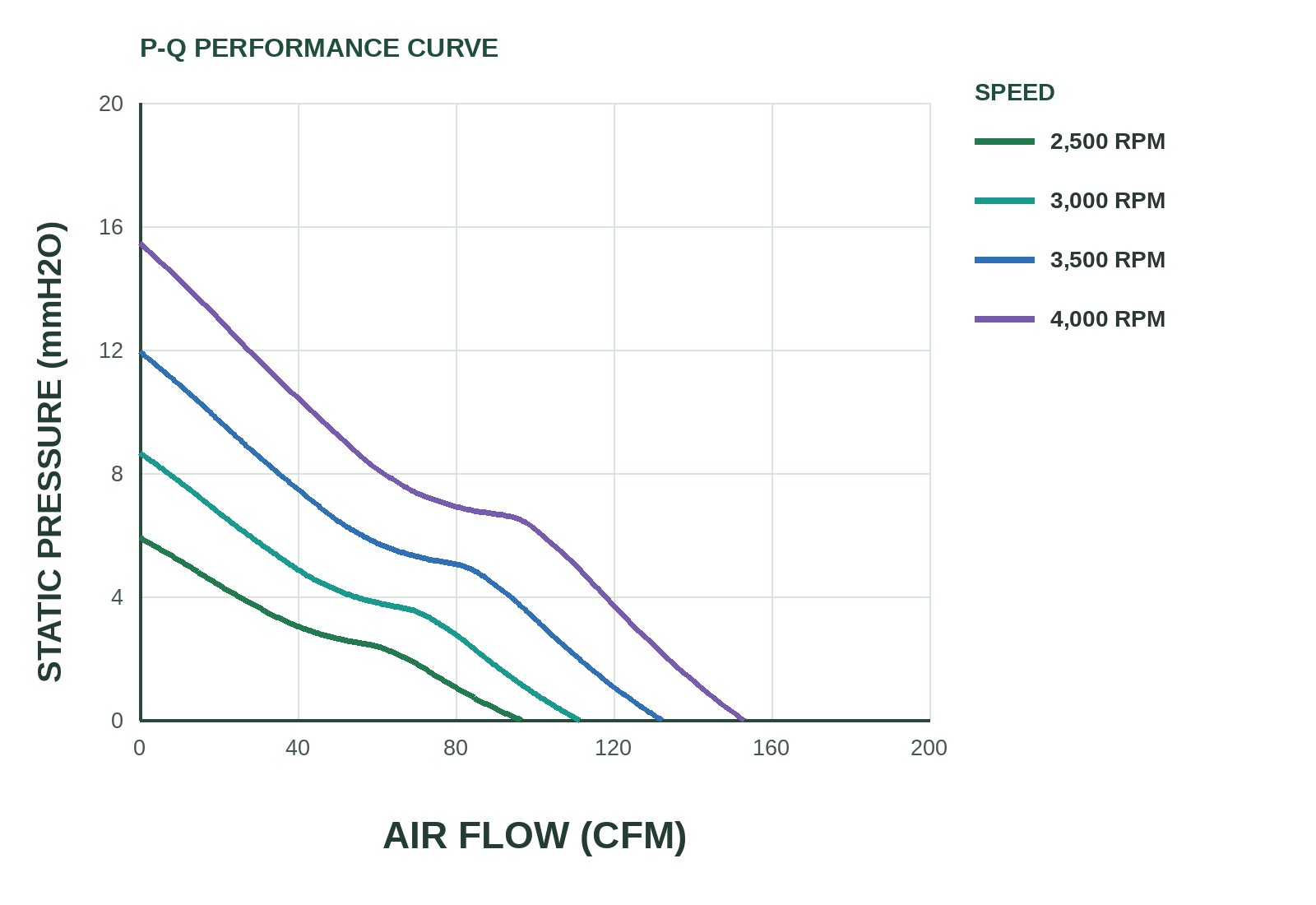
| MFE12038-LS | 220 | 200 ~ 240 | 3.2 | 2500 | 96.55 | 5.91 | 43.4 |
| MFE12038-MS | 220 | 200 ~ 240 | 3.2 | 3000 | 111.26 | 8.66 | 47.7 |
| MFE12038-HB | 220 | 200 ~ 240 | 3.2 | 3500 | 132.14 | 11.94 | 52.8 |
| MFE12038-HHB | 220 | 200 ~ 240 | 6.4 | 4000 | 152.89 | 15.46 | 54.5 |
Dimension Drawing
P&Q Curve
Signal Output Options
VPWM voltage speed control is an optional function for this series. FG / RDH / RDL / LD outputs depend on the complete part number.
| Signal | Direction | Function | Description |
|---|---|---|---|
| VPWM | Control Input | DC voltage speed control | EC series speed is set by an external DC control voltage, commonly 0-5 V or 0-10 V. The control line must share ground with the fan supply negative; input range, wire colour, impedance and minimum speed follow the complete part-number approval sheet. |
| FG / TACH | Status Output | Reports speed as a pulse train | Typically an open-collector/open-drain output with an external 4.7–10 kΩ pull-up; usually 2 pulses per revolution, RPM = FG Hz × 60 ÷ 2. Pull up to the host logic supply, never directly to the fan supply. |
| RDH / RDL | Alarm Output | Locked-Rotor Alarm Rotation Detector / Locked-rotor Alarm | RD is a locked-rotor status output — it does not indicate reverse rotation. RDH goes high when the fan is locked or stopped; RDL goes low. Usually an open-collector output; start-up delay and actual levels follow the complete part-number approval sheet. |
| LD | Alarm Output | Life Detection Life / Low-Speed Detection | Detects speed decay or fan ageing: the output goes low when speed falls to roughly 70% of rated. LD is not the same function as the RD locked-rotor alarm and is available on selected models only. |
Typical signal diagrams
FG / TACH
A continuous pulse train lets the host calculate speed. Usually an open-collector output; pulses per revolution, pull-up voltage and resistor must be confirmed per model.
VPWM
The external DC control voltage is applied to the VPWM lead and shares ground with the supply negative; speed rises from minimum to maximum with the control voltage. Wire colour and range follow the approval sheet.
LD
The output goes low when speed falls to roughly 70% of rated, indicating performance decay; LD differs from the RD locked-rotor alarm.
RDH / RDL
RDH is high on lock; RDL is low on lock. They differ only in polarity and both indicate whether the fan is locked or stopped; start-up delay and electrical ratings follow the complete part-number approval sheet.
Part Number Code
From left to right: MFE series, frame, thickness, speed code, bearing code, VPWM speed-control input and signal-output code. F, RDH, RDL and LD are model-dependent signal outputs; available combinations follow the complete part-number approval sheet.