
MFL17569
Product Specifications
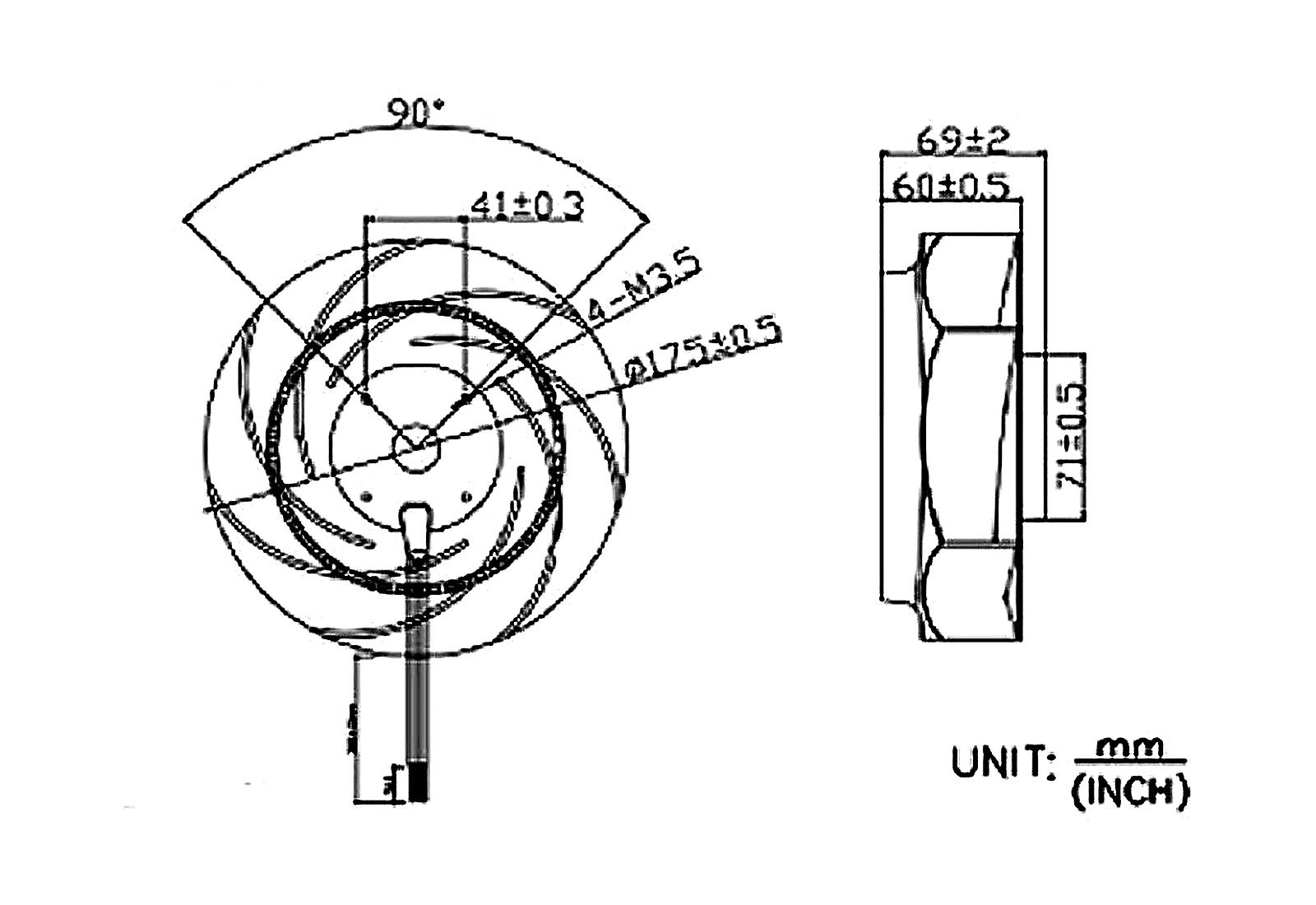
| Size | Ø 175 x 69 mm |
| Motor | Brushless DC |
| Voltage | 12V / 24V / 48V DC |
| Frame | plastic PBT UL94V-0 |
| Bearing Type | Ball Bearing / Sleeve Bearing |
| Operating Temperature | Ball Bearing: -10 ~ 70°C / Sleeve Bearing: 0 ~ 60°C |
| Life Expectancy | Ball Bearing: 50,000 hours at 25°C / Sleeve Bearing: 30,000 hours at 25°C |
Part Number & Specifications
| Model | Rated Voltage (V) | Operating Voltage Range (V) | Rated Current (A) | Input Power (W) | Speed (RPM) | Airflow (CFM) | Pressure (mmH₂O) | Noise (dB-A) |
|---|---|---|---|---|---|---|---|---|
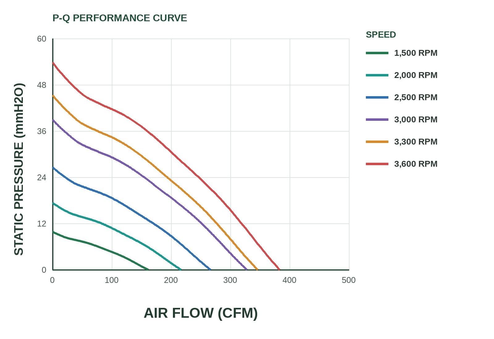
| MFL17569D1-LB | 12 | 7 ~ 13.8 | 1 | 12 | 1500 | 161.3 | 9.87 | 41.8 |
| MFL17569D1-MB | 12 | 7 ~ 13.8 | 1.3 | 15.6 | 2000 | 216.64 | 17.35 | 51.2 |
| MFL17569D1-HB | 12 | 7 ~ 13.8 | 2.5 | 30 | 2500 | 266.35 | 26.6 | 57.2 |
| MFL17569D1-HHB | 12 | 7 ~ 13.8 | 4 | 48 | 3000 | 327.6 | 38.95 | 61.2 |
| MFL17569D1-VHB | 12 | 7 ~ 13.8 | 4.5 | 54 | 3300 | 345.68 | 45.28 | 64.1 |
| MFL17569D1-HVB | 12 | 7 ~ 13.8 | 5 | 60 | 3600 | 382.75 | 53.8 | 65.8 |
| MFL17569D2-LB | 24 | 18 ~ 26.5 | 0.5 | 12 | 1500 | 161.3 | 9.87 | 41.8 |
| MFL17569D2-MB | 24 | 18 ~ 26.5 | 0.64 | 15.36 | 2000 | 216.64 | 17.35 | 51.2 |
| MFL17569D2-HB | 24 | 18 ~ 26.5 | 1.05 | 25.2 | 2500 | 266.35 | 26.6 | 57.2 |
| MFL17569D2-HHB | 24 | 18 ~ 26.5 | 1.7 | 40.8 | 3000 | 327.6 | 38.95 | 61.2 |
| MFL17569D2-VHB | 24 | 18 ~ 26.5 | 2.2 | 52 | 3300 | 345.68 | 45.28 | 64.1 |
| MFL17569D2-HVB | 24 | 18 ~ 26.5 | 2.7 | 64.8 | 3600 | 382.75 | 53.8 | 65.8 |
| MFL17569D4-LB | 48 | 36 ~ 54 | 0.25 | 12 | 1500 | 161.3 | 9.87 | 41.8 |
| MFL17569D4-MB | 48 | 36 ~ 54 | 0.5 | 24 | 2000 | 216.64 | 17.35 | 51.2 |
| MFL17569D4-HB | 48 | 36 ~ 54 | 0.75 | 36 | 2500 | 266.35 | 26.6 | 57.2 |
| MFL17569D4-HHB | 48 | 36 ~ 54 | 1 | 48 | 3000 | 327.6 | 38.95 | 61.2 |
| MFL17569D4-VHB | 48 | 36 ~ 54 | 1.25 | 60 | 3300 | 345.68 | 45.28 | 64.1 |
| MFL17569D4-HVB | 48 | 36 ~ 54 | 1.5 | 72 | 3600 | 382.75 | 53.8 | 65.8 |
Dimension Drawing
P&Q Curve
Signal Output Options
This series is available with the following signal functions (per complete part number):
| Signal | Direction | Function | Description |
|---|---|---|---|
| PWM | Control Input | PWM speed control | The industry-typical control frequency is 25 kHz ±10%. A 0% duty cycle may mean minimum speed or full stop, so a 20–100% control window is commonly recommended; confirm on the complete part-number approval sheet. |
| VPWM | Control Input | DC voltage speed control | EC series speed is set by an external DC control voltage, commonly 0-5 V or 0-10 V. The control line must share ground with the fan supply negative; input range, wire colour, impedance and minimum speed follow the complete part-number approval sheet. |
| FG / TACH | Status Output | Reports speed as a pulse train | Typically an open-collector/open-drain output with an external 4.7–10 kΩ pull-up; usually 2 pulses per revolution, RPM = FG Hz × 60 ÷ 2. Pull up to the host logic supply, never directly to the fan supply. |
| RDH / RDL | Alarm Output | Locked-Rotor Alarm Rotation Detector / Locked-rotor Alarm | RD is a locked-rotor status output — it does not indicate reverse rotation. RDH goes high when the fan is locked or stopped; RDL goes low. Usually an open-collector output; start-up delay and actual levels follow the complete part-number approval sheet. |
| LD | Alarm Output | Life Detection Life / Low-Speed Detection | Detects speed decay or fan ageing: the output goes low when speed falls to roughly 70% of rated. LD is not the same function as the RD locked-rotor alarm and is available on selected models only. |
Typical signal diagrams
FG / TACH
A continuous pulse train lets the host calculate speed. Usually an open-collector output; pulses per revolution, pull-up voltage and resistor must be confirmed per model.
PWM
Duty cycle sets the speed. Frequency, amplitude, usable duty range, minimum speed and input wiring must not be treated as universal values.
VPWM
The external DC control voltage is applied to the VPWM lead and shares ground with the supply negative; speed rises from minimum to maximum with the control voltage. Wire colour and range follow the approval sheet.
LD
The output goes low when speed falls to roughly 70% of rated, indicating performance decay; LD differs from the RD locked-rotor alarm.
RDH / RDL
RDH is high on lock; RDL is low on lock. They differ only in polarity and both indicate whether the fan is locked or stopped; start-up delay and electrical ratings follow the complete part-number approval sheet.
Part Number Code
From left to right: MFL series, size code, voltage code, speed code, bearing code, signal code and ingress protection. The code order matches the DC fan and blower series; available combinations follow the complete part-number approval sheet.